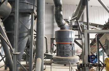
Control Grinding Mill With Sound
circuit diagram for ball mill using rtd sensor the information needed for mill control. Ball Mill Level RTD sound sensor is process control ball mill CGM Grinding Plant.

 WhatsApp)
circuit diagram for ball mill using rtd sensor the information needed for mill control. Ball Mill Level RTD sound sensor is process control ball mill CGM Grinding Plant.
Alarm Alarm Siren Audio Power Amplifier Battery Charger Battery Monitor Circuit Protection Crystal Oscillator Current Loop Data Communication Demodulator Dimmer Filter Flip Flop FM Transmitter LED Circuit Light Controller Light Sensor Linear Regulator Monitoring Motor Control Optoelectronics Oscillators Power Control PreAmplifier Remote
temperature control circuit diagram for ball mill using. Full text of quot;Holderbank Cement engineering bookquot; Internet Archive temperature control circuit diagram for ball mill using rtd sensor,Example Ampere meter 5% accuracy Temperature meter #177; 5#176; C Terminology Accuracy Maximum positive deviation,Noise (spurious voltage or current arising
mistors in Single Supply Temperature Sensing Circuits, DS00685. Finally, the signalconditioning path for the RTD system will be covered with application circuits from sensor to microcontroller. FIGURE 1: Unlike thermistors, RTD temperaturesensing elements require current excitation. RTD OVERVIEW The acronym RTD is derived from the
Digital temperature controller circuit and working Fig. 2 shows circuit diagram of the digital temperature controller. The circuit is built around microcontroller PIC16F877A (IC1), precision thermocouple amplifier AD8495 (IC2), Ktype thermocouple (connected at CON3), 16#215;2 LCD (LCD1), singlechangeover relay (RL1) and a few common components.
circuit diagram for ball mill using rtd sensor. circuit diagram for ball mill using rtd sensor. nbsp 0183 32 The thermistor has to be connected to a control circuit which can convert the resistance signal which again has to disconnect the motor Used in threephase motors The resistance in the sensor remains relatively low and constant over a wide temperature band and increases abruptly
Aug 29, 2019#0183;#32;A RTD or resistance temperature detector works by detecting the difference or an increase in the resistance of the sensor metal when it''s subjected to heat. This change in the temperature of the element being directly proportional to the heat, provides a direct reading of the applied temperature levels.
Jul 07, 2020#0183;#32;A widely used choice for a temperature sensor is the resistance temperature detector (RTD), a precision metal element usually made of pure or nearly pure platinum. A platinumbased sensor has a fully detailed, repeatable, and characterized resistanceversustemperature transfer function, so RTDs are widely used in scientific and instrumentation
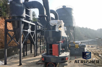
Circuit Diagram For Ball Mill Using Rtd Sensor. Circuit diagram for ball mill using rtd sensor traditional mills like ball mills, there was need to develop a mill that could grind ore to TECHNICAL NOTES 8 GRINDING R. P. King. Free consultation 40 years
Temperature Control Circuit Diagram For Ball Mill Using Electric Diagram Ball Mill. Circuit diagram for ball mill using rtd sensor electrical block diagram ball millenvironmental protection energysaving low costball mill electric motor diagram thesquarespoonmake a ball mill in 5 minutes 4 steps ake a ball mill in 5 minutes this is for all the
The Temperature Sensor LM35 series are precision integratedcircuit temperature devices with an output voltage linearly proportional to the Centigrade temperature. The LM35 device has an advantage over linear temperature sensors calibrated in Kelvin, as the user is not required to subtract a large constant voltage from the output to obtain
Get Price. sensor circuit diagram of automatic grinding machine sbm. temperature control circuit diagram for ball mill using rtd sensor . temperature control circuit diagram . Pin on Electronic Circuit Diagrams. Sep 22, 2017 We will make a Automatic Home cleaning Robot that only costs a small fraction of the ones in the market. This Robot can
In our daytoday life, we got used to implement different different types of sensor circuits using various types of sensors such as IR sensors, temperature sensor, pressure sensor, PIR sensor, and so, we observe PIR sensor circuit based automatic door opening system, LDR sensor circuit based automatic street light system, piezoelectric sensor circuit based power generation
Various CNC mill circuit diagrams and other DIY CNC mill information: Control: Jun 17, 20111: 5W Chinese PLL FM Transmitter With LCD Printed Circuit Board (PCB) Transmitters : 1: Simple test equipment to build: Test 1: A TwoWay Morse Practice Set: Misc : 0: Send Morse on your VHF Rig: RF 1: An endfed antenna, Lmatch coupler and resistive
Circuit Diagram Of Coal Mill Mining Machinery. Mining Mill Circuit Diagram. circuit diagram of mill ore. Adopting many advantages from various mills, and the ideal substitute of the traditional mill. Find out More of this Equiment . circuit diagram for ball mill using rtd sensor Mining . Contact Supplier
circuit diagram for ball mill using rtd sensor. Kolkata ball mill trunion temperature sensors. Older mill trunnion seals and bearing housings viewing ports temperature sensors newest seals and conical ball mill the eto grinding team proposed a price get details get price temperature sensor rtd for mill plant d e seal lubri ion sensors probe...
Vertical Roller Mill. Automatic control system makes remote control, low noise, and integrate sealing device stop dust spill and pollute the environment. diagram of a ball mill circuit . Second Hand Concrete Batching Plants For Sale In Malaysia. Modification And Change In Ball Mill.
3#216; WIRING DIAGRAMS 1#216; WIRING DIAGRAMS Diagram ER9 M 3~ 1 5 9 3 7 11 Low Speed High Speed U1 V1 W1 W2 U2 V2 TK TK Thermal Overloads TWO SPEED STAR/DELTA MOTOR Switch M 3~ 010V 20V 415V AC 420mA Outp uts Diagram IC2 M 1~ 240V AC 010V Outp ut Diagram IC3 M 1~ 010V 420mA 240V AC Outp uts These diagrams are current at the time of publication
NAT) is exceeded, the circuit can be switched off through a relay or amplifier, since the PTCsensor will have an extremely high ohmic value in the region of its response will have the same effect as a break in the circuit or a failure of the thermistor. TECHNICAL DATA Nominal response temperature 80 #176; to 180 #176;C in steps
Apr 22, 2016#0183;#32;Diode 1N4148 and variable resister of 1k ohm are used here to set a reference or threshold level for the sensitivity of heat. And the sensitivity of the circuit can be adjusted by rotating the knob. Working of the circuit is simple, when there is heat or increase in temperature to the level where it crosses the threshold set by Pot, Then the collector current increase and LED starts
Jan 02, 2008#0183;#32;concerning the thermistor temperature sensor, refer to Microchips AN685, Thermistors in Single Supply Temperature Sensing Circuits [ 7]. Finally, the signalconditioning path for the RTD system will be covered with application circuits from sensor to microcontroller. FIGURE 1: RTD Temperaturesensing Elements Use Current Excitation
For example, a class A sensor equipped with a coiled RTD element must maintain the specified tolerance from 100+450#176;C. When operated outside this temperature range, the sensor accuracy might default to class B. Sensors that meet ASTM E1137 grade A or grade B tolerance must maintain the specified tolerance from 200+650#176;C.
rtd of cement mill for dry cement plant. A raw mill is the equipment used to grind raw materials into quotrawmixquot during the manufacture of cement rawmix is then fed to a cement kiln, which transforms it into clinker, which is then ground to make cement in the cement millThe raw milling stage of the process effectively defines the chemistry and therefore physical properties of the finished
Because of the range of mill sizes available AG/SAG milling can often be accomplished with fewer lines than in a conventional rod mill/ball mill circuit. A diagram of types of AG/SAG . Chat Online; Digital Control Lab. For mining MillSlicer yields three independent volumetric fill level signals inlet
WhatsApp)